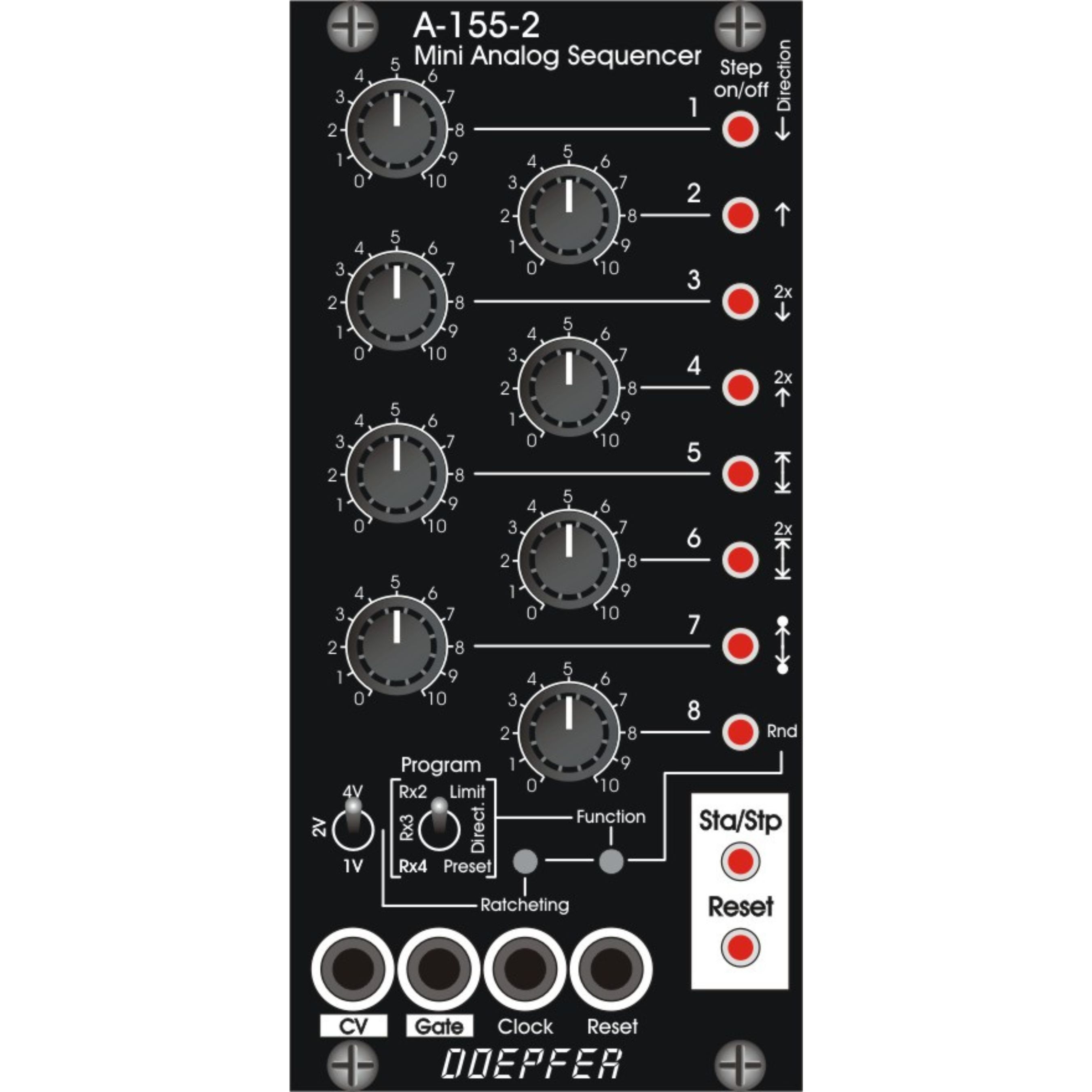
Module A-155-2 is a small, very compact designed analog sequencer with a lot of features. The sequence length is 8 steps. Each step has available a control for the adjustment of the control voltage for this step and an illuminated momentary switch (button). The buttons are used in the standard running mode to turn on/off the gate of the step in question (button illuminated = gate on, not illuminated = gate off). In combination with other controls at the bottom of the front panel the buttons are used for additional functions: depending on the position of the Program toggle switch the button Function is used to program the length of the sequence (switch position Limit), the running direction (switch position Direct.) or to call up the preset management (switch position Preset).
When function Direct. (Direction) is selected these running modes are available:
- Up
- Down
- 2 x Up (each step is played twice with the normal tempo, not to be confused with Ratcheting x2, see below)
- 2 x Down (each step is played twice with the normal tempo, not to be confused with Ratcheting x2, see below)
- Pendulum type 1 (start and end step are played twice)
- 2 x Pendulum type 1 (each step is played twice with the normal tempo, start and end step are played 4x)
- Pendulum type 2 (start and end step are played once)
- Random (Rnd)
When a function Preset is selected, the illuminated buttons are used to call up one of the 8 presets. In each preset these parameters are stored: active steps, running direction, length of the sequence, ratcheting. To call up one of the 8 stored presets, one has to push and hold the button Function and then operate short-time one of the buttons 1...8 while the toggle switch Program is in position Preset. To store the present parameters in one of the 8 presets the procedure is similar but one has to operate one of the buttons 1...8 for a longer time (~ 3 seconds).
Depending on the position of the Program toggle switch the ratcheting button is used to program the ratcheting feature (x2, x3, x4) individually for each step of the sequence (toggle switch Program in position Rx2, Rx3 or Rx4). In case that at the step in question another ratcheting is already programmed (e.g. x2 or x3 when x4 is chosen) the other ratcheting is overwritten (kind of radio button function between the ratchetings x2, x3 and x4). Details about the ratcheting function are explained at the module A-160-5.
The button Start/Stop is used to start or stop the sequence manually. Button Reset sets the sequence to the first step. For this also the external input Reset can be used.
The module does not feature a built in clock generator. Rather, an external Clock signal is used. The positive edge of the incoming clock signal triggers the advance of the sequence to the next step.
The voltage range of the control voltage generated by the module can be switched to 3 different ranges by the toggle switch Range: 0...+1V / 0...+2V / 0...+4V. The control voltage is available at socket CV. The voltage is not quantized. But there is an internal pin header available that outputs the data via Midi (note on/off from Midi note 36. Midi channel 1). It can be used to control a Midi-to-CV interface if quantized control voltages are required, e.g. the planned Micro-CV-Interface A-190-9).
The Gate signal appears at socket Gate. The pulsewidth of the gate signal is defined by the pulsewidth of the clock signal provided that ratcheting is not active at the step in question.
Controls and displays:
- 1...8 (rotary controls): manual adjustment of the control voltage for each step
- 1...8 (illuminated momentary switches/buttons): manual gate setting for each step, also used for special functions in combination with other controls (setting of first/last step, running direction, ratcheting)
- Range: toggle switch for selection of the control voltage range
- Program: toggle switch for selection of a function in combination with the buttons Ratcheting and Function
- Ratcheting: button for the programming of ratcheting in combination with the toggle switch Program
- Function: button for the programming of sequence length (Limit) and running direction (Direct.), as well as for the Preset management (Preset)
- Sta/Stp: button for the manual control of Start and Stop, in running state the LED of this button displays the state of the Gate output (i.e. it flashes in the rhythm of the Gate output)
- Reset : manual reset button
- CV : control voltage output
- Gate : gate output
- Clock: clock input, the pulsewidth of the clocjk signal defines the pulsewidth gate signal
- Reset: reset control input, reset type selectable via internal jumpers (e.g. positive edge triggers the jump to first step / positive leveltriggers the jump to first step and remains at first step as long as the reset input is high / waiting for the next positive edge of the clock signals before reset is carried out / ...)
Technical Details:
- Gate output voltage: about 0V/+10V
- required clock input level: min. +3V
- required reset input level: min. +3V
- max. clock frequency: >10kHz (e.g. for graphic VCO application)
- internal Midi output: Midi channel 1, Midi note range 36-48, 36-60 or 36-72 according to the setting of the range switch